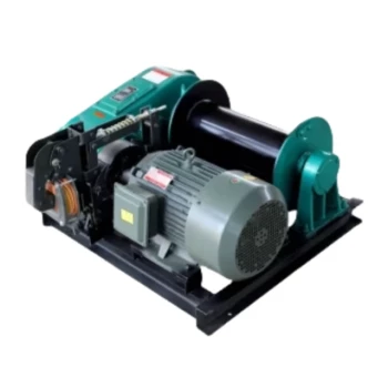
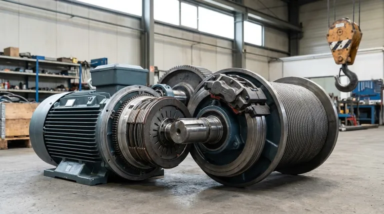
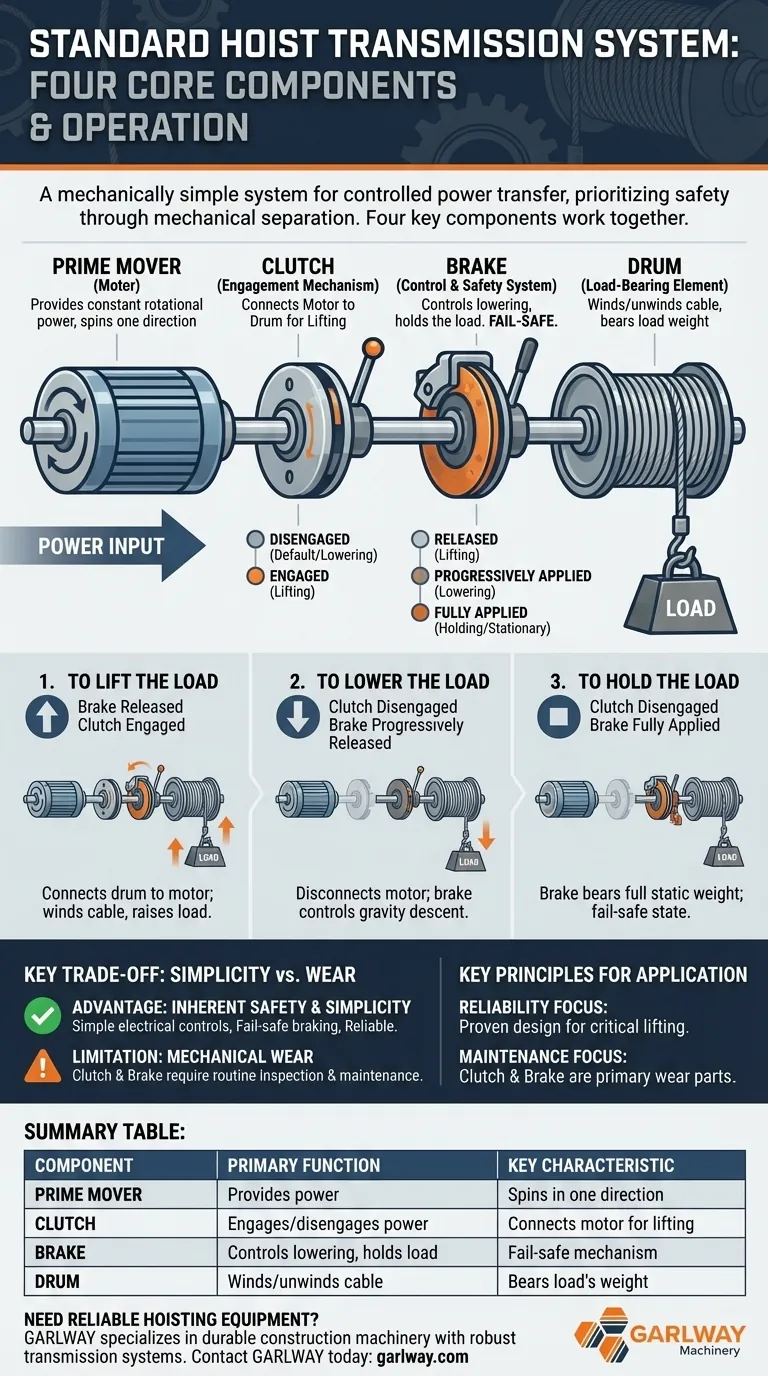
At its core, the standard transmission of a hoist is a mechanically simple system designed for controlled power transfer. It is built around four primary components: a prime mover (motor), a clutch, a brake, and a load-bearing drum. The prime mover provides constant rotational power, and the clutch and brake work in tandem to lift, lower, and hold the load securely.
The essential principle of this design is control and safety through mechanical separation. By using a prime mover that only spins in one direction, the system relies on a distinct clutch for lifting and a robust brake for lowering and holding, creating an inherently stable and predictable operation.
The Four Core Components of Hoist Transmission
To understand the system, we must first understand the role of each individual part.
The Prime Mover: The Source of Power
The prime mover is typically an electric motor or an engine. In this standard configuration, its defining characteristic is that it always rotates in the same direction at a relatively constant speed.
The Drum: The Load-Bearing Element
The drum is the cylinder onto which the wire rope or chain is wound. As the drum rotates, it either lifts the load by reeling in the cable or allows it to be lowered by reeling it out.
The Clutch: The Engagement Mechanism
The clutch is the critical link between the prime mover and the drum. When the clutch is engaged, it transfers the rotational power from the constantly spinning motor to the drum, causing the drum to turn and lift the load.
The Brake: The Control and Safety System
The brake is attached directly to the drum assembly. Its primary function is to apply frictional force to slow, stop, or securely hold the drum (and therefore the load) in place. It is the sole mechanism for controlling the load during lowering.
How the Components Work Together
The genius of this system lies in the coordinated sequence of engaging and disengaging the clutch and brake.
To Lift the Load
To begin lifting, the brake is released, and the clutch is engaged. This action connects the drum to the powered motor, forcing the drum to rotate and wind the cable, raising the load.
To Lower the Load
To lower the load, the clutch is disengaged, disconnecting the drum from the motor. The operator then carefully and progressively releases the brake, allowing gravity to pull the load downward in a controlled descent. The speed of descent is managed entirely by the brake.
To Hold the Load Stationary
When the load is at the desired height, the clutch is disengaged, and the brake is fully applied. The brake now bears the full static weight of the load, preventing any unwanted movement. This is the system's default and safest state.
Understanding the Key Trade-off: Simplicity vs. Wear
This classic design is valued for its reliability, but it's important to understand its inherent trade-offs.
The Advantage: Inherent Safety and Simplicity
The mechanical nature of the system is a significant advantage. Because the motor does not need to reverse, the electrical controls are simpler. More importantly, many brake systems are designed to be "fail-safe," meaning they automatically engage if power is lost, preventing the load from dropping.
The Limitation: Mechanical Wear
Because the clutch and brake are responsible for all power transmission and load control, they are subject to significant mechanical wear. The friction surfaces degrade over time, requiring routine inspection and maintenance to ensure continued safe operation.
Key Principles for Your Application
Understanding this structure helps you assess hoisting equipment more effectively.
- If your primary focus is reliability: The standard transmission's mechanical simplicity and fail-safe braking offer a robust and proven design for critical lifting tasks.
- If your primary focus is operational maintenance: Recognize that the clutch and brake are the primary wear components and must be the focus of any preventative maintenance program.
By grasping how these four components interact, you can better operate, maintain, and specify the right hoisting equipment for any goal.
Summary Table:
| Component | Primary Function | Key Characteristic |
|---|---|---|
| Prime Mover (Motor) | Provides constant rotational power | Spins in one direction only |
| Clutch | Engages/disengages power to the drum | Connects motor to drum for lifting |
| Brake | Controls lowering and holds the load | Fail-safe mechanism for safety |
| Drum | Winds/unwinds the cable or chain | Directly bears the load's weight |
Need reliable hoisting equipment for your construction projects? GARLWAY specializes in durable construction machinery, including winches and hoists designed with robust transmission systems for safety and longevity. Our solutions are built for the demanding needs of construction companies and contractors worldwide.
Contact GARLWAY today to discuss your specific lifting requirements and discover how our expertise can enhance your site's safety and efficiency.
Visual Guide
Related Products
- Electric Hoist Winch Boat Anchor Windlass for Marine Applications
- Electric and Hydraulic Winch for Heavy Duty Applications
- Hydraulic Winding Engine Harbor Freight Winch
- Portable Cement Mixer with Lift Concrete Machine
- 12000 lb Electric Boat Trailer Winch with Windlass Anchor Warn
People Also Ask
- What are the main benefits of a boat anchor winch? Boost Safety & Efficiency for Your Vessel
- What is the general user satisfaction with boat anchor winches? A Game-Changer for Boaters
- How does an electric anchor winch work? Power, Safety, and Reliable Operation Explained
- What are the operational differences between electric hoists and winches? A Guide to Safe Lifting vs. Pulling
- What are the advantages of a windlass type anchor winch? Achieve Precise, Rapid Anchoring for Your Vessel