At their core, the short circuit and open circuit methods are fundamental electrical diagnostic techniques used to test the integrity of the wiring and connections leading to and from a sensor. The short circuit method involves intentionally creating a low-resistance path to test for unwanted connections, while the open circuit method involves disconnecting a component to test for breaks in the electrical path.
The crucial insight is that these methods primarily diagnose the pathway, not the sensor itself. They are used to definitively answer the question: "Is the problem in the wiring, or is it in the component?"
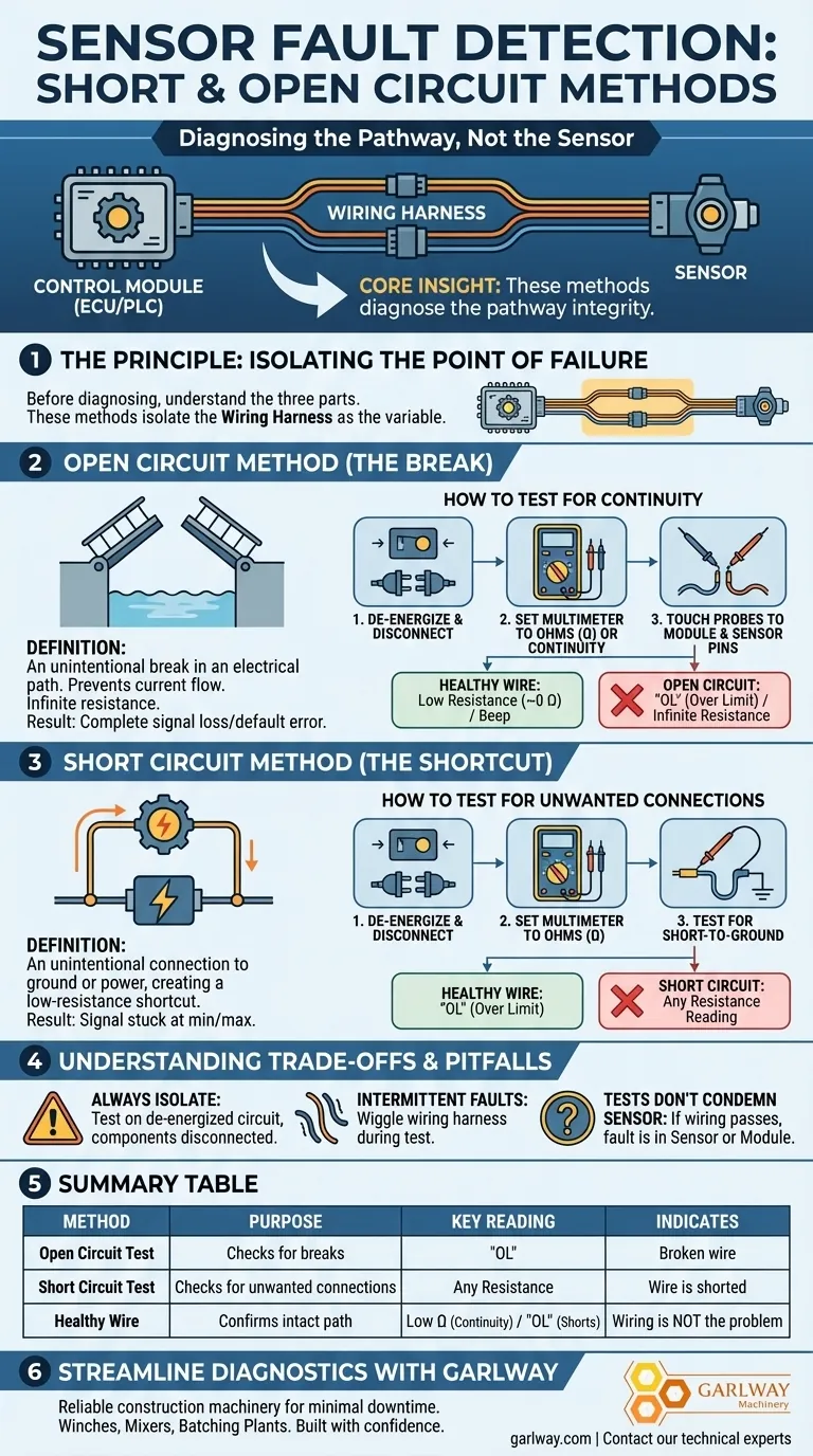
The Principle: Isolating the Point of Failure
Before diagnosing a sensor, you must understand that a sensor system has three main parts: the control module (like an ECU or PLC), the wiring harness that connects everything, and the sensor itself. A failure in any of these parts can produce the same symptom. These methods isolate the wiring harness as the variable.
What is an Open Circuit?
An open circuit is an unintentional break in an electrical path. Think of it as a raised drawbridge; electricity cannot flow across the gap.
This results in infinite resistance, preventing current from reaching its destination. In a sensor circuit, this often manifests as a complete loss of signal or a default error reading.
How to Test for an Open Circuit
The goal is to test for continuity, which is the presence of a complete path for current to flow.
- De-energize the circuit and disconnect the connectors from both the sensor and the control module.
- Set your multimeter to the resistance (Ohms Ω) or continuity setting.
- Touch one probe to the pin on the control module connector and the other probe to the corresponding pin on the sensor connector.
- A healthy wire will show a very low resistance (close to 0 Ohms) and the multimeter may beep. A reading of "OL" (Over Limit) or infinite resistance indicates a break in the wire—an open circuit.
The Counterpart: Finding a Short Circuit
A short circuit is the opposite of an open. It is an unintentional connection between two points in a circuit that should not be connected, creating a path of very low resistance.
What is a Short Circuit?
Think of a short circuit as a shortcut for electricity. The current takes this easier path, bypassing the intended component (like the sensor).
The most common types are a short-to-ground, where a signal wire touches the vehicle's chassis or another ground path, or a short-to-power, where it touches a power wire. This often results in a signal that is stuck at its minimum or maximum value.
How to Test for a Short Circuit
This test checks if a wire is electrically connected to something it shouldn't be.
- De-energize the circuit and disconnect the connectors from the sensor and the control module.
- Set your multimeter to the resistance (Ohms Ω) setting.
- To test for a short-to-ground, touch one probe to the signal wire's pin and the other probe to a known good ground (like the negative battery terminal or a clean point on the chassis).
- A healthy, isolated wire should show "OL" (Over Limit). Any resistance reading indicates an unwanted connection—a short circuit.
Understanding the Trade-offs and Pitfalls
These methods are powerful but require careful application to avoid misdiagnosis or causing further damage to sensitive electronics.
Always Isolate the Component
Testing for resistance or continuity must be done on a de-energized circuit with components disconnected. Measuring resistance on a live circuit can damage your multimeter and the control module.
Intermittent Faults are Common
A wire may only have an open or a short circuit when it is moved or under certain temperature conditions. While testing, it's a common professional practice to gently wiggle the wiring harness to see if the multimeter reading changes, which would reveal an intermittent connection issue.
These Tests Don't Condemn the Sensor
If the wiring passes both the open and short circuit tests, you have successfully proven that the wiring harness is intact. This strongly suggests the fault lies either with the sensor itself or the control module, but it does not tell you which one.
Making the Right Choice for Your Goal
Use these methods as a logical process of elimination to systematically find the root cause of a sensor fault.
- If your primary focus is a complete loss of signal (e.g., a 0V reading): Start with an open circuit test, as a broken wire is the most likely cause.
- If your primary focus is an illogical or fixed signal (e.g., stuck at 5V): Perform a short circuit test to check if the signal wire is shorted to a power or ground source.
- If both the open and short circuit tests pass: You have effectively ruled out the wiring, allowing you to confidently focus your diagnosis on the sensor or the control module.
By methodically testing the circuit's integrity, you transform guesswork into a precise and efficient diagnostic strategy.
Summary Table:
| Method | Purpose | Key Multimeter Reading | Indicates |
|---|---|---|---|
| Open Circuit Test | Checks for breaks in the wire (no continuity). | "OL" (Over Limit) | A broken wire or connection. |
| Short Circuit Test | Checks for unwanted connections (e.g., to ground/power). | Any resistance reading (not "OL") | A wire is shorted. |
| Healthy Wire | Confirms the wiring path is intact and isolated. | Low resistance (~0 Ohms) for continuity; "OL" for shorts. | Wiring is not the problem. |
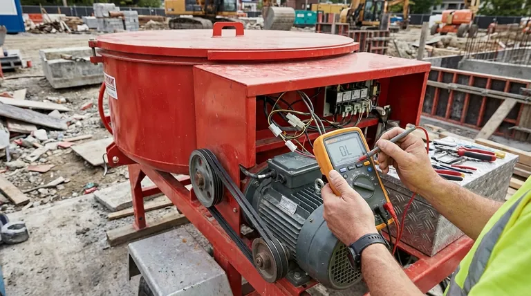
Streamline Your Equipment Diagnostics with GARLWAY
Isolating electrical faults is critical for keeping your construction machinery—from winches to concrete batching plants—operational. Just as you methodically test for shorts and opens, you need reliable components.
GARLWAY specializes in durable construction machinery and components designed for minimal downtime. Our products, including robust winches, efficient concrete mixers, and high-capacity batching plants, are engineered for the demanding environments that construction companies and contractors face daily.
Let us help you build with confidence.
Contact our technical experts today to discuss how our solutions can enhance the reliability and efficiency of your projects.
Visual Guide